
- full source code and binaries for linux-x64 and win32
→ available on Github - → live Demo
Eine Deutsche Übersetzung findest du hier.
Motivation
Trying to provide at least some real-time 3D graphics on websites has always been a pain. Before WebGL finally got adopted by Microsoft and Apple, there were numerous technologies struggling to get accepted as the de facto 3D standard for the web.
Not willing to support all of them, I asked myself the Question:
What if I don’t use any 3D rendering technology at all?
Obviously I’d have to do all the rendering myself.
Sounds challenging? Well, it depends on what you are trying to accomplish. If it’s just some basic projection, a simple lightsource and rudimentary texturing - it’s not as hard as you might expect.
Having learned 3D graphics using OpenGL2.1, I had a hard time getting used to the “new” freely programmable pipeline in nowadays OpenGL / WebGL.
I didn’t appreciate the definition of free in these versions, because it is not free like in you may do this, actually it is you have to!
Although I already have written some OpenGL 4.0 code, my shaders were copypasted one-liners.
That said, I worked on this for two reasons:
- finally understand, what shaders do and what can be done by using them
- find out, if the performance might actually be good enough, to use it as a fallback, if there is no WebGL available
Just to point that out: I do know, that there is 3D rendering support in Flash and Microsofts Silverlight. I just don’t think any of these technologies is suitable for today’s web requirements – especially if you are going for portability and don’t want to implement the same thing using several different proprietary technologies.
Prerequisite
What you need to get started rendering is exactly the same, you would need for using hardware accelerated rendering - nevertheless I’d like to list it here.
- a vertex model of the object(s) you’d like to render
- texture mapping coordinates
- normal vectors for triangles
a vertex model of the object(s) you’d like to render
Since I was going to render a globe, this was pretty straight forward. All it took was a 5120 sided icosahedron. This is quite a high trianglecount for an object to be rendered in plain software, but the next lower trianglecount mathematical possible would have been only 1280 triangles, which looked rather like something you would roll for a tabletop game, than like a sphere.
Although this makes the texture mapping a bit harder in the end, I prefer the icosahedrons shape to the usual approximation of a sphere, because all its sides are identical.
The wireframe of a standard sphere approximation looks unbalanced to me, it’s faces become infinitely small at the poles.
I’m sure there is a surprisingly simple formula to get my icosahedron calculated in code, but I just ran some regex replacements on a model exported as wavefront .obj from blender. Because I have absolutely no clue about how to map a world maps image on an icosahedron, I was relying on it anyways.
texture mapping coordinates
As I mentioned earlier, this is plain black magic to me. To apply a texture to anything else than a rectangle, you need a mapping of your objects triangles to the parts of your texture you want do have filled into each specific triangle.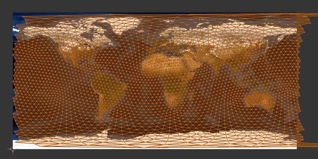 It seems there is no perfect solution for an icosahedron based sphere, but just hitting UV unwrap was sufficient for my project.
As you can see, an icosahedron is not an optimal object for sphere texture mapping, either. I doubt there is any.
As long as you use a rectangular area to be mapped to a sphere, the upper and lower end of the texture will be mapped to the poles, thus mapping the entire area to just a few triangles.
Surprisingly blender generated some mapping coordinates larger than one. These were meant to wrap around the texture. I have chosen to ignore them, as this would require some extra “if”s for each and every pixel to be rendered and I didn’t expect my approach to be fast enough for this (in the end I was right).
normal vectors for triangles
Again, you can easily calculate normal vectors in your own code (cross-product), but as long as your objects have a static shape which gets only morphed by the modelview matrix (I’ll get to this later), you don’t need to.
Applying the same matrix to the normal vectors will always keep them in sync.
Normal vectors come in handy for quite a few things. They help you to determine if a triangle is inside- or outside facing, they are needed to apply light calculations and they help you to detect triangles which can’t be seen from the cameras point of view, because they are backfacing.
This (backface culling) is the only technique I used normal vectors for. CPU based texture mapping is a very expensive process, so every triangle you do not need to draw helps speeding up your rendering.
Of course you can only use this on non transparent objects, otherwise backfacing triangles can and should be seen.
I got everything except for the texture out of blender so I was ready to dive into the rendering process.
ToDo:
- project vertices from 3D object space to 2D screen coordinates
- remove invisible triangles
- calculate which screen pixel actually lie within a triangle
- map texture pixels to screen pixels
All these steps are normally performed by the hardware. At least for step two till four we are more or less used to the hardware acting as a black box. I am no exception to that rule, so I had no idea how to do this, but lets start at the beginning.
Projecting Vertices from 3D Object Space to 2D Screen Coordinates
It does not matter whether you are going to use hardware acceleration or not, you still have to provide certain matrices, to project your vertices.
Well… that’s not 100% true, in fact you could do your vector algebra without using matrices at all, but that won’t speed up the process in any way.
So I used the same matrices I would have used for WebGL.
It greatly enhances performance if we pre-multiply all matrices (at least for all vertices undergoing the same transformation):
combined = VPcorr * projection * camera * model
Explained from right to left:
model: represents all the transformations which should be applied only to a singe object, or even only parts of it. (typically rotation, translation and scaling)
camera: if your camera is moving, you should translate and rotate this matrix. This keeps the camera independent from everything else. If you are nerdy you could apply the opposite transformation to all objects, like if the camera takes three steps forward in some direction, you could also move the world three steps in the opposite direction. The camera matrix is just a convenient construct.
projection: this is where the magic happens. I won’t go into the details, if anyone is interested in that, read the corresponding abstracts in the OpenGL documentation. This is the place were I learned to set this matrix up component by component.
If you are going do do an orthographic projection, there isn’t much more like scaling and translating represented by this matrix.
If you set up a perspective projection like I did, it gets a bit more complicated, but again, I’ll spare you the details.
There is one detail left to mention: Without using the hardware accelerated rendering pipeline, you need to divide each and every x and y coordinate by their corresponding z coordinate. The hardware does this implicit for you. So if you forget to do this in the software-only case, your perspective projection will look more like a broken orthographic projection.
So what about VPcorr?
I’m glad you paid attention. Now that you ask for it: This is another calculation you do not need to perform, if you use hardware rendering, because the hardware automatically fits your virtual projection output to screen coordinates.
The coordinates you get out of the projection are still located between minus one and one at the x and y axis. Obviously this is of little use to put pixels onto a canvas with always positive coordinates and an origin at zero/zero in the corner.
VPcorr scales the coordinate system by half the canvas size in each direction and moves the origin to the middle of the canvas.
From that point on, we can use these coordinates directly as canvas coordinates. We still have a z axis coordinate left, which we will use later on, but for the task of getting canvas coordinates, we don’t need it anymore.
Now that we have a combined matrix, what are we gonna do with it?
The hardware accelerated case: We wouldn’t even have to combine these – instead it is sufficient to provide them to a vertex shader, which does the calculations for us.
Really doing it yourself: Multiply each and every vertex of your model by the combined matrix, buffer them and don’t forget to divide by z in the end.
The result in the buffer is your vertices projected to screen coordinates for one frame.
If your Object moves, you’ll obviously have to do it all over the next frame, but this is not the part which is going to heat up your CPU.
Removing invisible Triangles
Because the rendering speed is largely dependent on how many triangles you are going to draw, it’s a good idea to remove those, which otherwise would be drawn over by a triangle nearer to the camera.
As long as you’re not working with transparencies, the simplest technique you might implement is backface culling. All you have to do is:
- apply modelview and projection to your normal vectors
- calculate the dot product between normal and camera location
- drop all triangles for which this results in a value larger than zero
it represents an angle larger than 90°, which you can interpret as showing the camera its backside
Sounds easy? I have to confess, I somehow messed this step up. Applying the projection matrix leaded to strange results, so I only applied the modelview matrix and calculated the dot product.
This is inaccurate because a perspective projection also alters the normal vectors. In my case I was left with more backfacing triangles than my culling implementation could detect.
If your backface culling has flaws, or you are working with transparencies, OR you’re working with objects more complex than geometric primitives like cubes or spheres – in short: always – there is one more thing you need to do:
You have to sort all triangles by their position at the z axis.
If you don’t do this and just draw all triangles by their position in your objects buffer, you’ll end up drawing triangles that are farther away from the camera on top of triangles that are close by. If you are a sensitive person this might make you throw up - your brain has never seen something like this (not kidding).
I simply used qsort with a callback that compares z coordinates.
Don’t get me wrong, sorting triangles by their z coordinates does not remove any more triangles, which don’t need to be drawn. It just saves you from drawing them at the wrong point in time.
They’re still there, but you just made sure that triangles that are closer to the camera, are drawn over them.
At least the result on screen is correct now.
Calculating which Screen Pixels actually lie within a Triangle
The performance grave starts here. I never really thought about this problem, although I must have heard something about this at university. I wasn’t eager to dig up that old stuff, so I tried to crack this one with my own head.
Lets start by defining a minimal screen aligned bounding box, which contains the triangle.
We get it by taking the minimal and maximal x and y coordinates defining the triangle. They define two edges of the bounding box, which is enough to iterate over each pixel.
To draw the triangle we must test for each pixel of the bounding box, if its inside or outside of the triangle. But how to test for it?
The trivial approach is taking all three edge vertices and convert them to vectors by subtracting them. (Lets name them A, B, C)
v1 = A - B
v2 = B - C
v3 = C - A
These vectors rotate (mathematically incorrect) around the center of the triangle. Wasn’t there some formula to check on which side of a vector a point is located?
Given that, a point which is on one side of all three vectors has to be inside. The relevant side depends on the way the vectors rotate around the center and which side it actually is.
Searching for some code snipplet I could adopt, I stumbled upon a site which describes something much better.
The author suggests to do a coordinate system transformation instead, resulting in fewer instructions.
If you take one vector as origin and the subtraction of the origin from the remaining two as unit vectors, you get a shiny new coordinate system. This new coordinate system is only cartesian, if the angle at the origin was 90°, but that doesn’t matter.
You can still define every point in that coordinate system by a linear combination of its unit vectors.
Actually that’s how a coordinate system is defined.
In pseudocode it looks like this:
P = u * v1 + v * v2
With P being a point, u & v some factors and v1 & v2 your unit vectors.
The beauty about this is, that you can prove each pixel inside the triangle to meet the following conditions:
(u >= 0) && (v >= 0) && (u + v < 1)
To get P you only need to subtract your new origin, u & v are harder to get, but it still takes less effort (measured in instructions) to test if a point is part of a filled triangle.
If you are interested, you should read the original site.
By knowing the pixels belonging to a triangle, we could fill it with a constant color. But what about texture?
Read on!
Mapping Texture Pixels to Screen Pixels
Again, initially I had no idea how to do this. That is, until a had the factors
u & v from the last step. The mapped triangles on the texture may look totally distorted, rotated and … in other words, messed up, but what goes for the triangles on screen, is still valid for the mapped triangles.
If we convert them to an origin and two unit vectors, like we did before, we can use the very same factors u & v and do a linear combination of the unit vectors and these factors.
That’s really all we need to get the corresponding texture pixel for each screen pixel. The texture pixel is still relative to the origin, but that can be fixed by adding the vector back, we subtracted earlier to get to the new origin.
Knowing this, it seems pretty much obvious, that testing for pixels inside a triangle and mapping texture color to it, should be done inside the same loop.
What about light?
Yes you are right. All of my pixel mapped like this have the full intensity of the texture. To keep it short, light and reflections are doing math with your triangles normal vectors, a vector pointing to your lightsource(s) and a vector pointing to your camera. Calculate angles, weight them, add them and multiply the result with your texture color and you can achieve all sorts of virtual light impressions.
Having a virtual sun might have been interesting, but my code is already slow enough… .
This doesn’t look like nowadays computer games. Could you apply some anti-aliasing?
Surely I could. It’s easy, but at the same time it blows up computation time. I give you an idea on how to do it.
We could start by not testing if a pixel is part of a triangle, but if a sub-pixel is. Instead of stepping through the bounding box pixel by pixel, we would only advance half a pixel, a quarter and so on. Since this is a two dimensional coordinate system, your computation time goes up squared.
To get a better texture quality, we would need not to copy a single pixel, but to sample the whole n-pixel environment with a weighted gauss kernel for example.
Again this would be a horrible thing to do on the CPU.